Understanding Torque Converter Overheating on Wheel Loaders During Stockpile Work
Stockpile work keeps a wheel loader in constant direction changes with a full bucket and near-continuous hydraulic demand, and that is hard on the torque converter. The converter is a fluid coupling: it multiplies engine torque and passes power to the transmission, and while it does that the oil absorbs energy and gives off heat. Once heat builds faster than the cooling system can remove it, fluid temperature climbs past the safe range and the converter is overheating.
Operators notice it as sluggish hydraulics, weak travel, and a gauge reading that keeps climbing. In the shop it shows up as varnished fluid, hardened seals, and clutch wear. For a fleet, the cost lands as unplanned downtime, higher repair bills, and components replaced early.
A temperature gauge alone will not tell you what is wrong. Two tests do most of the work. A stall test measures converter and engine behavior under load; a cooler flow check shows whether oil is actually circulating through the cooler. Run together, they separate a converter fault from a cooling restriction, and usually early enough to avoid a rebuild.
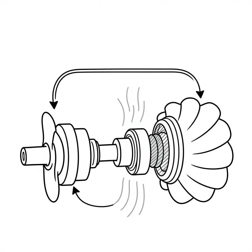
The schematic traces the oil path. It leaves the impeller (the pump), drives the turbine, passes through the stator in the center, and returns to the pump. The shaded area is where energy is lost as heat, most of it at the stator and at the turbine’s fluid exit during stall. Crowd a bucket into a pile and the turbine slows to near zero while the engine keeps turning the pump, so nearly all the input energy leaves as heat instead of wheel torque. That is why cooler flow and short stall cycles matter on a loader.
Why Stockpile Work Drives Torque Converter Overheating
A torque converter has no gears or shafts. It moves power through oil between an impeller, a turbine, and a stator. Hold the turbine still while the impeller spins at engine speed and the converter is fully stalled: almost none of the engine power leaves as useful work, so nearly all of it becomes heat in the oil. No duty cycle stalls a converter harder than stockpile work.
Crowding a face or stockpile means pushing and lifting against a mass that barely moves. The operator holds full throttle while the machine creeps forward, lifts with the bucket still buried, then makes the short run to the truck. The converter stays in its high-slip range far longer than in a general earthmoving cycle, and the sump temperature rises faster than the cooler can pull it back down.
The main contributing factors
- Prolonged stall against the pile. Crowding at full engine rpm with the wheels barely moving pins the converter at maximum slip; nearly 100 percent of input power becomes heat instead of tractive effort.
- Repeated short loading cycles. Tight V-shaped cycles of about 30 to 60 seconds leave the cooling circuit almost no time to recover, so the sump temperature ratchets up cycle after cycle instead of settling.
- Dust and high ambient temperature. Fine silica dust packs the radiator and cooler fins, and hot ambient air raises the air-side baseline, shrinking the temperature difference the cooler needs to reject heat.
- Restricted airflow and low flow. Blocked or bent cores, missing baffles, damaged shrouds, and leaks all starve the cooler. A worn charge pump or internal leakage lowers cooler flow the same way.
Any one of these is manageable. Stacked together, as they are in continuous stockpile work, they make overheating a predictable condition rather than a random fault.
Stall Test Procedure for Diagnosing Torque Converter Overheating
A stall test loads the converter to its maximum multiplying condition and measures the engine speed that results. On a wheel loader it is the fastest way to tell a converter problem from a transmission, engine, or cooling-circuit problem. Follow the sequence exactly; a deviation gives a meaningless reading and can damage the drivetrain.
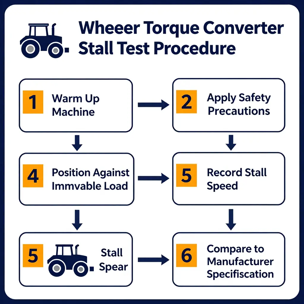
Step-by-Step Stall Test
- Warm up the machine. Idle the engine until the transmission fluid reaches normal operating temperature, typically 60-80 C (140-175 F). Record the fluid level and confirm the cooler lines are warm, not cold. Cold fluid is viscous and will produce an artificially high stall speed.
- Apply safety precautions. Park on level, firm ground with the parking brake set. Install the articulation lock, clear all personnel from the machine and the load, and check that the area behind and ahead is free of obstacles. Never run the test with anyone near the bucket or the tires.
- Position the machine against an immovable load. Lower the bucket and crowd it hard against a solid bank, a heavy immovable block, or a braked tow machine so the wheels cannot rotate. The loader must be unable to move forward or reverse under full power.
- Select the correct gear and apply full throttle. Place the transmission in the gear specified by the manufacturer, usually first forward. Hold the service brake firmly, then depress the throttle fully and hold it for no more than 10-15 seconds. Watch the tachometer stabilize.
- Read the recorded stall speed. Note the stabilized engine rpm at full throttle. Repeat the test in the opposite direction and record both values for comparison.
- Compare against the manufacturer specification. Check the readings against the stall speed range in the service manual, then allow the transmission to cool before any further testing.
What the Readings Indicate
| Reading | Likely Condition |
|---|---|
| Stall speed higher than specification | Converter slipping internally, worn stator clutch, low converter charge pressure, or a converter-to-engine mismatch |
| Stall speed lower than specification | Engine down on power, restricted air or fuel delivery, dragging brakes, or a restricted converter charge circuit |
| Stall speed within specification but overheating persists | Cooler flow restriction, clogged oil-to-air cooler, failed cooling fan, or degraded fluid |
A high stall speed points to the converter itself or to low charge pressure, and it raises heat generation fast; that is often the root cause of overheating in stockpile cycling. A low stall speed usually points upstream, to the engine or to brake drag, and it can hide a converter fault by keeping the unit below its rated load. Confirm with a charge pressure and cooler flow check before condemning the converter.
Stall Test and Cooler Flow Diagnostic Reference Table
Use this grid alongside the OEM service manual. Put the machine on level ground, set the brakes, warm the fluid to normal operating temperature, and record each value at high idle. Specs vary by model and vintage, so check the manufacturer’s chart before condemning a component.
| Measurement / Test | Normal Range or Spec | Reading Too High | Reading Too Low | Most Likely Cause |
|---|---|---|---|---|
| Stall speed (converter stall test, high idle, brakes applied) | 1,850-2,050 RPM (model-specific) | Converter or clutch pack slipping; worn stator freewheel | Engine derate, low fuel, restricted air intake, worn converter | If high: internal slippage in converter/drive. If low: engine power or converter charge loss |
| Converter outlet pressure | 40-70 psi (275-480 kPa) at high idle | Restricted return or cooler/bypass blockage | Internal converter leak, worn seal rings, weak charge pump | Low charge flow or downstream restriction; check pump output and seals |
| Cooler inlet pressure | Within 10-15 psi (70-100 kPa) of converter outlet | Plugged cooler core or kinked inlet line | Upstream leak or failing charge pump | Restriction between converter and cooler blocks flow |
| Cooler outlet pressure | 5-20 psi (35-140 kPa) | Internal bypass valve stuck closed | Bypass valve stuck open, worn cooler, aerated fluid | Large inlet-to-outlet drop signals a restricted core |
| Cooler flow rate | 8-15 GPM (30-57 L/min) | Bypass valve stuck open (flow not routed through cooler) | Plugged cooler, collapsed hose, worn pump | Low flow is the most common root cause of overheating |
| Transmission fluid temperature (sump, stabilized duty) | 176-230 F (80-110 C); warn at 248 F (120 C) | Cooler restriction, low flow, over-stalling, high ambient | Not reaching temp; light load or cold-start | Rising temp with normal flow points to over-stalling; with low flow, points to cooler blockage |
How to Read the Pattern
- High stall speed plus high fluid temperature almost always means converter or clutch pack slippage is generating heat faster than the cooler can reject it.
- Low cooler flow with normal pressures points to a clogged cooler core or a collapsed line, not a pump failure.
- A wide inlet-to-outlet pressure drop across the cooler confirms a restriction: flush or replace the core.
- Low charge pressure at every port sends you to the charge pump and internal seal rings instead of the cooling circuit.
Cooler Flow Testing Methodology
Before blaming the torque converter, test the cooling circuit. A cooler flow test shows whether hot oil is reaching the cooler and returning to the sump. Run it with the machine warm and the oil at operating temperature so the readings repeat.
Measuring Transmission Cooler Flow Rate
Connect a calibrated flow meter (or a graduated container and a stopwatch) to the cooler return line at the transmission.
- Warm the oil to normal operating temperature.
- Run the engine at the specified test rpm.
- Measure return flow for 60 seconds and compare it against the OEM specification.
Flow below spec means a flow problem. Record the number; you will need it to isolate the fault.
Identifying a Restricted or Internally Bypassing Cooler
A restricted cooler shows up as low return flow while converter outlet pressure climbs. If the internal bypass opens early, oil skips the cooler core entirely, so flow at the hose looks normal but the temperature drop across the cooler is almost nil.
Compare inlet and outlet temperature. A healthy cooler sheds heat; a bypassing one does not, and that gap is the quickest clue.
Checking for a Plugged Cooler or Collapsed Hose
- Inspect hoses for kinks, soft spots, or a collapsed inner liner.
- Feel for a cold cooler core with a hot inlet: a sure sign of plugging.
- Watch the flow meter while flexing the hose; a sudden jump in flow confirms a collapsed hose.
Interpreting Converter Outlet vs Cooler Inlet Pressure
Measure both points with the oil hot. A large gap between converter outlet pressure and cooler inlet pressure means a restriction between them, often a blocked fitting or a caked cooler. A small gap with low return flow points downstream to a plugged hose or cooler.
Read the pressure gap together with the flow number before pulling any parts.
Reading the Temperature Curve
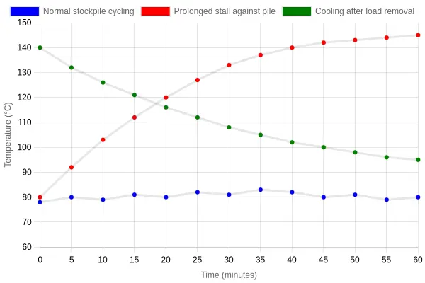
The chart plots transmission fluid temperature against time for three wheel loader conditions. How the curves diverge says more about converter heat than any single gauge reading.
The Three Series
Normal stockpile cycling (blue). In routine load-and-carry work the fluid holds a narrow band between roughly 78 and 83 C. The converter is slipping, but the cooler keeps pace.
Prolonged stall against a pile (red). Hold the bucket against an immovable face with the throttle in and the curve climbs almost linearly. With no forward motion and little airflow, the converter dumps nearly all engine power into the oil as heat, and the cooler cannot reject it fast enough.
Cooling after load removal (green). Release the load and start moving again, and temperature falls in a decay curve, steep at first and then flattening. The faster that line drops, the better the cooler flow and heat rejection.
Series Data Used to Render the Chart
| Time (min) | Normal cycling (C) | Prolonged stall (C) | Cooling after load removal (C) |
|---|---|---|---|
| 0 | 78 | 80 | 140 |
| 5 | 80 | 92 | 132 |
| 10 | 79 | 103 | 126 |
| 15 | 81 | 112 | 121 |
| 20 | 80 | 120 | 116 |
| 25 | 82 | 127 | 112 |
| 30 | 81 | 133 | 108 |
| 35 | 83 | 137 | 105 |
| 40 | 82 | 140 | 102 |
| 45 | 80 | 142 | 100 |
| 50 | 81 | 143 | 98 |
| 55 | 79 | 144 | 96 |
| 60 | 80 | 145 | 95 |
Chart Configuration
- Chart type: line
- Title: Transmission Fluid Temperature Over Time
- X-axis: Time (minutes), 0 to 60
- Y-axis: Temperature (degrees Celsius), scaled 60 to 150
- Datasets: Normal stockpile cycling (blue), Prolonged stall against pile (red), Cooling after load removal (green)
- Legend: Enabled, three clearly separated entries
- Styling: Light gridlines, labeled axes, no heavy text overlays
What the Divergence Means on the Job
The gap between the blue and red lines is the point. In normal cycling, heat in equals heat out. In a stall, heat in keeps climbing while heat out is capped by cooler capacity and available airflow. When the red curve crosses into the 120-130 C range and the green recovery curve flattens instead of falling sharply, cooler flow is restricted or the converter is slipping more than it should. Log the numbers and compare across machines, and a struggling cooling circuit shows up long before a seal or bearing fails.
Prevention and Maintenance Best Practices
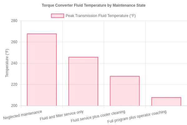
Overheating rarely appears out of nowhere. It builds over weeks of stockpile work as the fluid ages, cooler fins clog, and operators hold the machine against the pile a few seconds too long. A steady maintenance routine and a few better habits keep converter temperatures where they belong.
Start with the Right Fluid at the Right Level
The fluid carries heat away from the stator and clutch packs. Use the OEM-specified fluid and keep the level in the middle of the hot-running range, checked with the engine at operating temperature on level ground. Too little fluid starves the converter and cooler; too much aerates it; either one sends temperatures climbing. Change fluid and filters on the recommended interval rather than waiting for a symptom.
Keep the Cooling System Clean
Clean airflow does more than anything else to prevent torque converter overheating. Dust, chaff, and woody debris from bulk materials pack radiator and oil cooler fins faster than most operators expect. Clean the cores regularly, daily in high-dust stockpile work, and check that the fan, shroud, and foam seals are intact so air is pulled through the cores rather than around them.
Inspect Hoses and Fittings
Bulging hoses and weeping fittings rob flow and hide leaks. At every service, check transmission cooler lines for hard spots, chafing, and loose clamps, and repair damage before it becomes a roadside failure. A small restriction in a return line can add 20 to 30 degrees of heat to the whole circuit.
Coach Operator Technique
Stall time is the largest heat source. Approach the pile smoothly, fill the bucket in one clean pass, and avoid holding the machine against the stockpile while waiting for a truck. Partial throttle when positioning and a short idle in neutral between cycles both help.
Build a Simple Schedule
| Task | Interval |
|---|---|
| Check fluid level and color | Daily |
| Clean radiator and cooler cores | Daily to weekly (by dust) |
| Inspect hoses, clamps, fittings | Every 250 hours |
| Fluid and filter change | Per OEM interval (often 500-1000 hours) |
| Thermostat and fan drive check | Annually |
None of these steps costs much on its own. Together they hold peak temperatures inside the normal range.
Transmission Cooling Circuit: Flow at a Glance
It helps to know how the fluid travels through the system. The diagram shows the loop: oil leaves the torque converter, drops into the transmission sump, is pushed through the cooler, and returns by the return line to start again.
The arrows show flow direction at each stage. The highlighted point marks where a narrow passage, kinked hose, or partly blocked fitting can throttle the whole circuit. Once it pinches down, heat builds faster than the cooler can shed it, which is how converters overheat during stockpile stall work.
If any link in the loop starves flow, everything downstream runs hotter. Keep the path clear and the cooler can do its job.
FAQ: Torque Converter Overheating, Stall Testing, and Cooler Flow on Wheel Loaders
What is a normal stall speed?
Stall speed is the highest engine rpm you reach with the converter turbine held still, the machine in gear, and full throttle applied against a load. Most wheel loaders spec somewhere around 1,800 to 2,200 rpm, depending on the manufacturer and transmission. Compare your reading to the service manual rather than a generic figure. A reading more than about 10 percent outside spec usually means a converter, transmission pump, or engine problem.
How hot is too hot for transmission fluid?
Most powershift transmissions in wheel loaders run between about 80 degrees C (176 F) and 110 degrees C (230 F) during normal operation. Sustained temperatures above roughly 120 degrees C (248 F) accelerate fluid oxidation and shorten clutch, seal, and bearing life. If converter outlet temperature climbs above 130 degrees C (266 F), stop the machine and investigate before the fluid breaks down. The table below is a quick reference for converter outlet temperature.
| Condition | Converter outlet temperature | Recommended action |
|---|---|---|
| Normal | 80-110 C (176-230 F) | Continue operating and monitor |
| Caution | 110-120 C (230-248 F) | Reduce load and check cooler flow |
| Overheat | Above 120 C (248 F) | Stop, idle in neutral, and diagnose |
Can I keep operating when the converter overheats?
No. The heat goes straight into the clutches, seals, and bearings. Keep working and you risk burnt clutch plates, warped components, and a transmission rebuild. Reduce the load, put the machine in neutral, and idle so the pump keeps circulating fluid through the cooler. Resume only after the temperature is back to normal and you know what caused it.
How often should the cooler be cleaned?
Clean the transmission cooler and its radiator core at every major service interval, and any time fluid temperatures start to climb. In dusty stockpile work, inspect and blow out the fins daily or weekly; airborne material packs the core quickly and blocks airflow. A practical rule is to clean the cooler whenever you clean the engine radiator. Log airflow and fluid temperature trends to confirm the cleaning is working.
What causes low cooler flow?
Low cooler flow usually comes from a restricted or clogged cooler core, a worn transmission pump, a collapsed or kinked hose, or internal leakage in the converter and valve body. Debris shed by worn clutches can plug the cooler circuit too. Measure flow and pressure at the cooler lines to pinpoint the restriction, then clean, repair, or replace the affected component. Restoring correct cooler flow is the most reliable way to control torque converter overheating in heavy stockpile work.